
Definition of Illustrator?
What is Adobe Illustrator?

Adobe Illustrator is a professional vector-based design and drawing program. Used as part of a larger design workflow, Illustrator allows for the creation of everything from single design elements to entire compositions. Designers use Illustrator to create posters, symbols, logos, patterns, icons, etc.
Vector vs. Raster
Computer graphics fall into two main categories: vector graphics and raster graphics. Understanding the difference between the two helps you create, edit, and import artwork appropriately.
What are vectors?
Drawing programs such as Adobe Illustrator create vector graphics, which are composed of lines and curves defined by mathematical objects called “vectors.” Vectors describe a graphic according to its geometric characteristics. For example, a bicycle tire in a vector graphic is drawn using a mathematical equation for a circle with a certain radius, set at a specific location, and filled with a specific color. You can move, resize, or change the color of the tire without losing graphic quality because the underlying equations will compensate for your actions.
A vector graphic is resolution-independent, that is, it can be scaled to any size and printed on any output device at any resolution without losing its detail or clarity. As a result, vector graphics are the best choice for type (especially small type) and bold graphics that must retain crisp lines when scaled to various sizes.
Getting Started with Illustrator
Working with Objects
The Pen Tool
Color, Swatches, and Gradients
Working with Type
Creating a Batman Logo
I invite you to try Skillshare Premium for free for 14 days!
There are over 34,000 lessons, taught by creatives from all over the world for free. There are no obligations. You can cancel at any time. Try it now
Getting Started with Illustrator
All of Your Basics and More
Illustrator’s menu and toolbox layout is consistent with its other siblings in the Adobe Suite. If you have ever used Photoshop or PageMaker before, using Illustrator should feel intuitive. If you have never used any Adobe product before, however, the interface can be a bit dizzying.
Illustrator’s interface can be easily broken down into small categories which can be more easily understood. We will first begin with the main toolbox on the left-hand side of the screen and from there we will work our way around the workspace.
The key components we will be covering are the following:
- The toolbox
- The Color palette
- The Transparency palette
- The Stroke palette
- The Gradient palette
- The Layers palette
Some of the following information was obtained from “Illustrator 10 for Windows and Macintosh (Visual Quackster Guide),” a book by Elaine Weinmann and Peter Lourekas.
The Toolbox
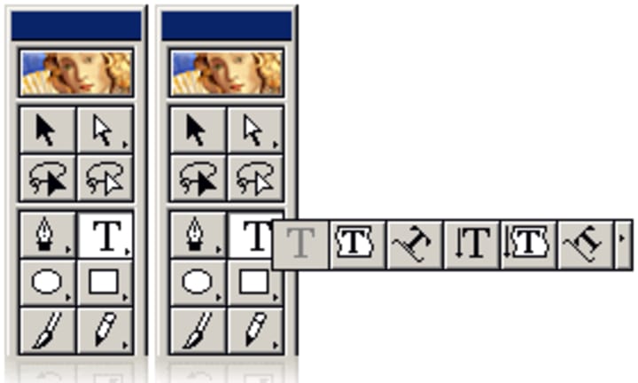
The main toolbox is located on the left-hand side of the screen by default. The toolbox holds most of the tools that you will use. Illustrator has a total of 53 tools to choose from, but not all of them are immediately visible. Tools marked with a little triangle in the lower right-hand corner of their icon have additional, related, tools available. To access these related tools, click and hold on a tool’s icon. Please note that the exact location of these tools does change from version to version of Adobe Illustrator, but tools never disappear.
Selection Tools
The first set of tools we’ll discuss is the Selection tool set. These tools allow you to manipulate only the objects you need and not every other object on the artboard.
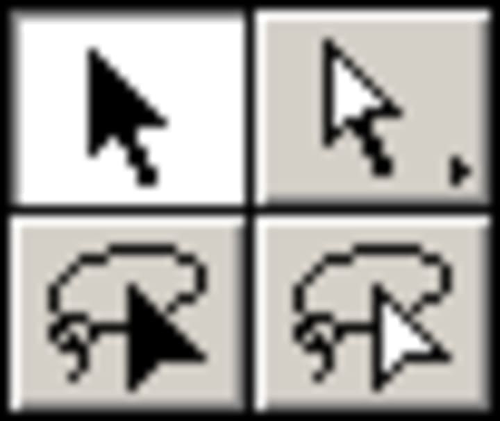
The primary Selection tool (the “black arrow” tool) is used for choosing whole objects on the artboard. These objects are usually created by one of the Draw tools. Once the object is selected, it can then be manipulated. When selecting an object using this tool, you will normally find the object enclosed in a rectangle called a “bounding box.”
Then there is the Direct/Group Selection tool (the “white arrow” tool). Almost every object created in Illustrator is made up of “anchor points.” These anchor points are basically dots in a plane that make up a line, with the caveat that these anchors also help define the way the line will bend. The Direct Selection tool allows you to manipulate one or more of those anchors to change your object to achieve a desired shape.
The last two Selection tools are both “lasso” tools and work exactly the same as their “arrow” counterparts. The only difference is that they are able to select more arbitrary shapes, rather than just rectangles and squares, when selecting objects and anchors.
Drawing Tools
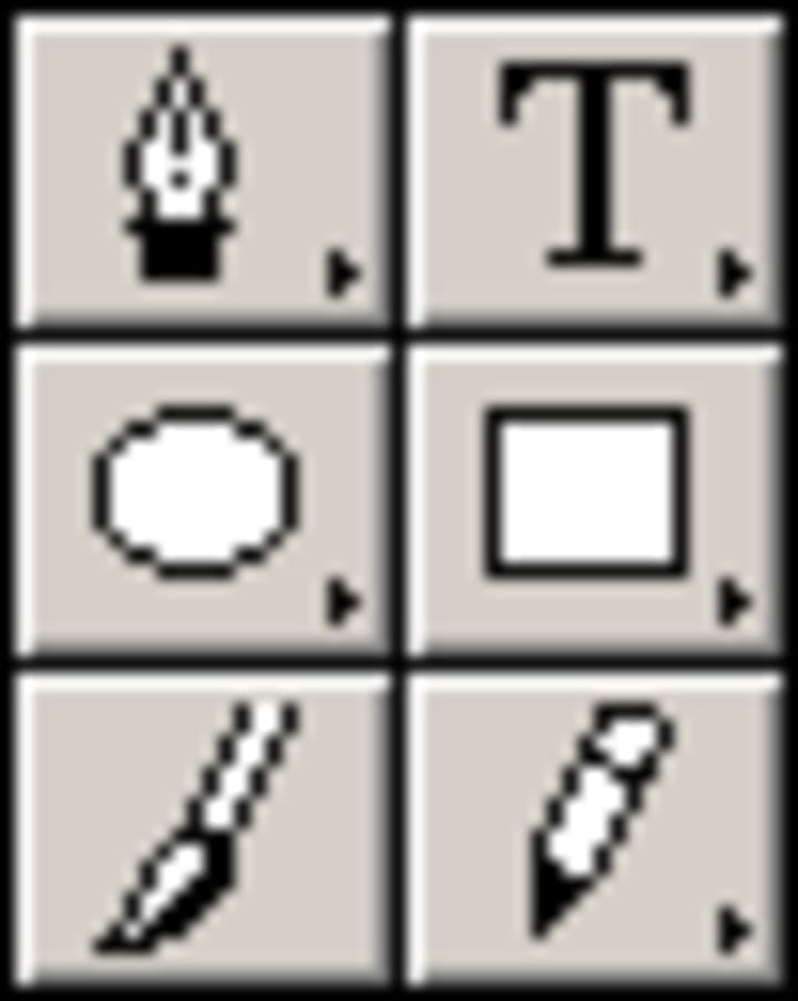
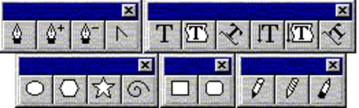
The first tool in this tool set is the Pen tool. Do not let its name fool you! The Pen tool does draw lines, but in a unique manner. The Pen tool is one of the most useful, yet complicated, tools to use in Adobe products. Marking two points on the artboard with the Pen tool creates a straight line, but you can also adjust the line to create a curve by manipulating the anchor points. The expanded Pen tools allow you to add and subtract anchor points for an object. The “caret arrow” converts a corner point to a curve or vice versa.
The second Draw tool is the Type tool. It allows you to place text somewhere on the screen, but the expanded Type tools offer many more possibilities for positioning text. The first expanded tool constrains the text within an object that you have created. The second causes text to follow a path that you have created. The path can be anything from a simple square to a curvy line dancing all around the artboard. The final three expanded Type tools do the same things as the previous three, except that the resulting text is vertical instead of horizontal.
The third Draw tool set is the set of Shape tools. Clicking and dragging while using these tools creates the indicated shapes immediately, while clicking once brings up a list of options that can be changed to create an object more to your specifications.
The last two Draw tools are Paintbrush tool and the Pencil tools. These tools draw lines on the artboard. The Paintbrush tool is used for calligraphy, scatter art, or patterned brushstrokes. The attributes for the Paintbrush tool can be changed by double-clicking on its icon. The Pencil tool is for freestyle line drawing (as opposed to the Pen tool). The expanded Pencil tools offer further options: the Smooth smooths out edges in an object and the Erase tool erases sections of an object’s path.
Manipulation Tools
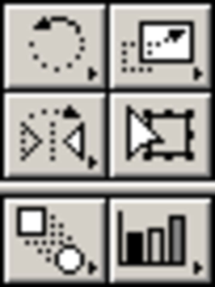
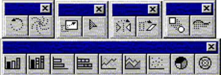
The first Manipulation tool we’ll go over is the Rotation tool, which rotates an object around its axis of rotation. The expanded Rotation tool is the Twirl tool, which stretches and spins shapes into unique designs.
The second tool is the Scale tool. Scaling changes the size of an object (you can constrain the new object to the original proportions, or not, as you see fit). The expanded Reshape tool reshapes objects by adding or subtracting anchor points.
The Reflect tool reflects an object over an axis. The expanded Skew skews an object.
The Free Transform tool rotates, scales, reflects, shears, distorts, or changes perspective for an object. This tool is a freely manipulable way to affect objects in all of the ways that the above tools do, all in one convenient location.
The Blend tool blends two or more objects, and their colors, to achieve effects that are otherwise hard to create. The Trace tool traces silhouettes.
The last Manipulation tool we’ll discuss is the Graph. This tool is not really a manipulation tool per se, and in fact in later versions of Adobe Illustrator, it doesn’t even appear in the Manipulation tool section. Rather obviously, the Graph tool and its expanded options allow you to insert a variety of graphs into your document.
Other Tools
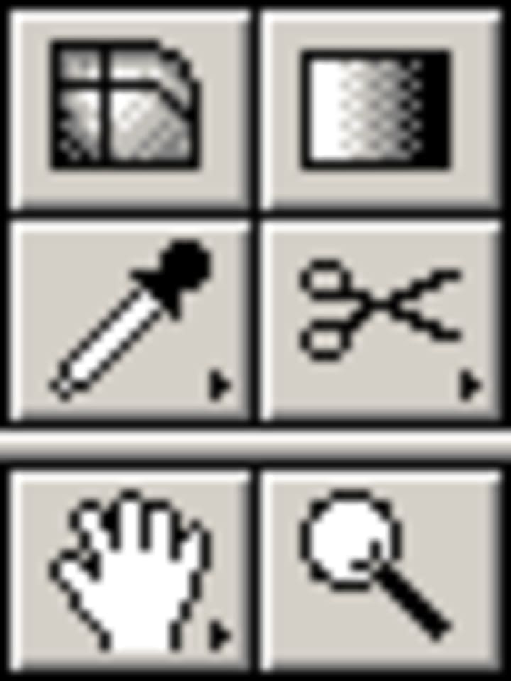
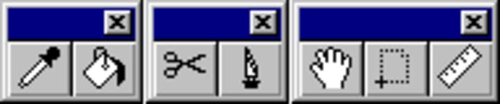
Other tools include the Eyedropper tool, which allows you to sample a color from anywhere on the artboard and reuse that color somewhere else, and the Paint Bucket, which fills objects with the currently selected color. The Scissors tool in Illustrator is not for cutting and pasting, as normal! Instead, the Scissors tool cuts object paths into two; the Knife tool is very similar to the Scissors tool in that it cuts up objects into two rather than splitting a single path. The Hand tool lets you move your current location on the artboard, the Page tool defines the printable area for your artboard, and the Measure tool measures the distance between any two points.
Color Tools
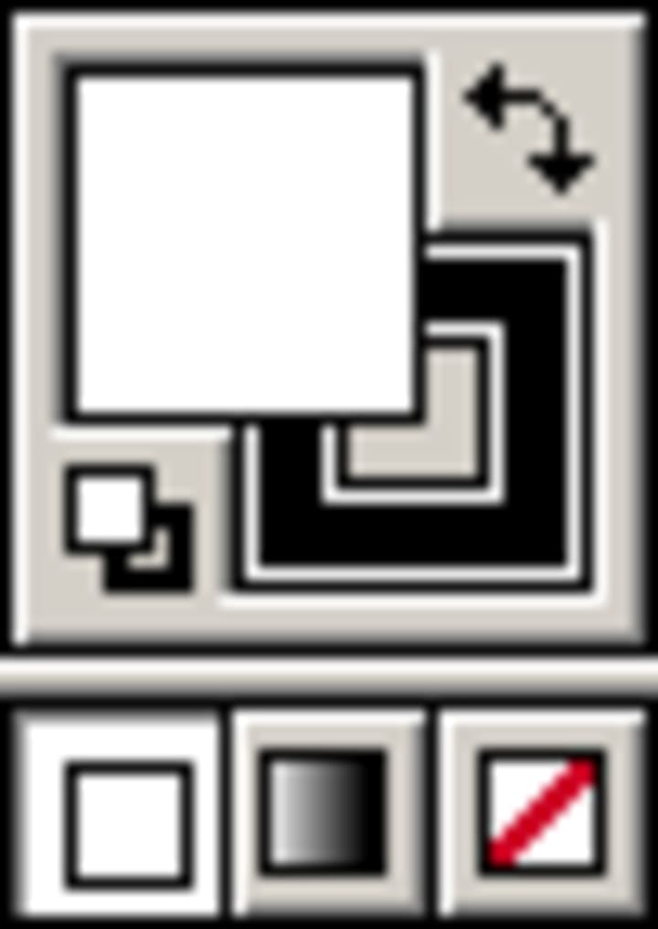
The last tool we’ll discuss is the Color Picker control. The solid square shows the current fill color, while the framed square indicates the current stroke color. The tiny black and white squares in the lower left reset the Color Picker to default colors.
The bottom three icons indicate whether the chosen colors will be solid, gradients, or transparent.
The Palettes
The Color Palette
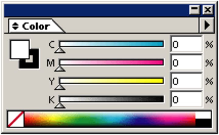
The Color palette is used for defining fill and stroke colors. A different Color palette will be displayed, depending on which color scheme you pick (RGB or CMYK). The example Color palette is for the CMYK color scheme. Colors can be chosen from the color spectrum or defined exactly by numerical values in the right-hand fields. As with the Color Picker, the fill color is represented by the solid square in the upper left corner while the stroke is represented by the framing square beneath the solid one.
The example Color palette does not display an “Out of Web” or “Out of Gamut” warning. “Out of Web” means that the color you are trying to use is not capable of being displayed on the Web. If you are concerned about Web-safe colors, you can click on a small cube that will show up, and use the dialog that appears to choose the closest Web-safe substitute. “Out of Gamut” means that the color will not be printed in the exact same shade as it appears on the screen. A triangle icon with an exclamation mark will appear to allow you to choose a proper substitute.
The Transparency Palette
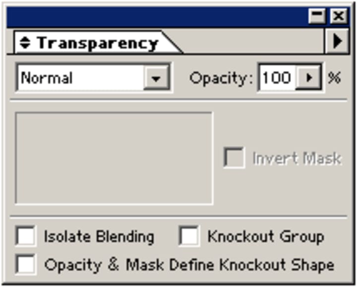
The Transparency palette is used to change the blending mode and opacity of individual objects, groups, or layers.
The Stroke Palette
The Stroke palette is used to manipulate stroke thickness for objects.
The Gradient Palette
The Gradient palette helps with creating gradients within an object or adjusting a current gradient. The default colors for the gradient are black and white, but they can be adjusted by dragging colors from the Color palette to the Gradient palette’s slider. Which way the gradient comes falls and how far colors extend can also be manipulated.
The Layers Palette
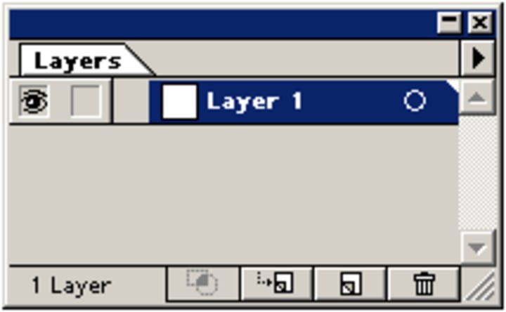
The Layers palette in Illustrator acts the same as Layers palettes do across the entire Adobe Suite. You can add or delete, select, restack, hide or show, lock or unlock, change view, or dim an individual layer, sublayer, group, or individual object.
I invite you to try Skillshare Premium for free for 14 days!
There are over 34,000 lessons, taught by creatives from all over the world for free. There are no obligations. You can cancel at any time. Try it now
Working with Objects
Creating Shapes
To create an object in Illustrator, just select the appropriate Shape tool and either click once where you want the center of that object to be or click and drag, creating your object as you drag. If you click only once, a box will pop up that will ask you want the dimensions of your object to be. Depending on the particular object, it may also ask for more information, such as how many sides or points you want for a polygon or star. Sounds simple, right? But what about those really complex objects you might want to make?
To create an object in Illustrator, just select the appropriate Shape tool and either click once where you want the center of that object to be or click and drag, creating your object as you drag. If you click only once, a box will pop up that will ask you want the dimensions of your object to be. Depending on the particular object, it may also ask for more information, such as how many sides or points you want for a polygon or star. Sounds simple, right? But what about those really complex objects you might want to make?
In truth, using simple shapes, the Rotate and Scale tools, and the Pathfinder and Align palettes, we are able to create fairly complex objects. Think about how many objects around you are really just combinations of rectangles and ellipses… a lot, right?
I invite you to try Skillshare Premium for free for 14 days!
There are over 34,000 lessons, taught by creatives from all over the world for free. There are no obligations. You can cancel at any time. Try it now
The Pen Tool
Much More Than a Pen
The Pen tool is probably the most powerful tool in Adobe Illustrator. It allows the artist to create shapes with freeform curves, and with time and skill, most curves found in the “real world” can be duplicated using the Pen tool.
Before you start using the Pen tool, there are some things to note in that it doesn’t work the way you think it would. It does not draw wherever you drag, like the Paintbrush or Pencil tools. Notice if you click and drag immediately, all it seems to do is make a straight line with dots at each end. Before you can understand the Pen tool, you need to know what that line is: a path. (The following information was obtained from the Illustrator online help).
About Paths
A path is made up of one or more straight or curved “segments.” The beginnings and ends of each segment are marked by “anchor points,” which work like pins holding a wire in place. You change the overall shape of a path by editing its anchor points, and control a curve by dragging the “direction points” at the end of the “direction lines” that appear at anchor points.
A path is either open, like an arc, or closed, like a circle. For an open path, the starting and ending anchor points for the path are called its “endpoints.”
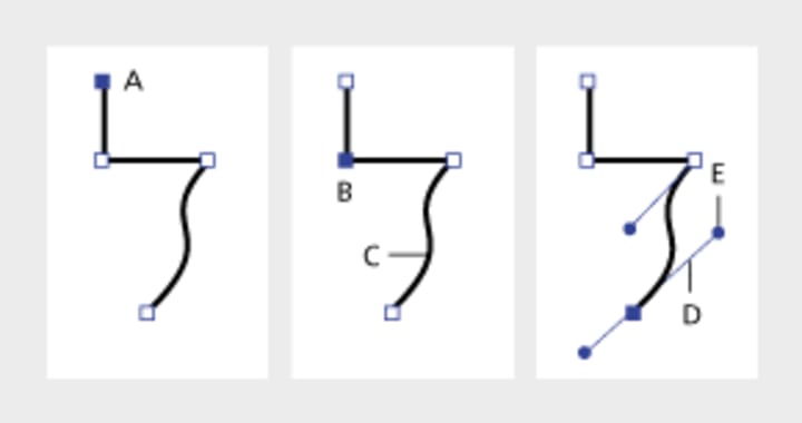
A. Selected (solid) endpoint
B. Selected anchor point
C. Curved path segment
D. Direction line
E. Direction point
Paths can have two kinds of anchor points”corner points” and “smooth points.” At a corner point,”a path abruptly changes direction. At a smooth point, however, path segments are connected as a continuous curve. You can draw a path using any combination of corner and smooth points. You can always change point types if need be.
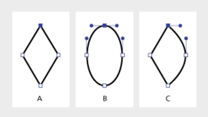
A. Four corner points
B. Same point positions using smooth points
C. Same point positions combining corner and smooth points
Don’t confuse corner and smooth points with straight and curved segments! A corner point can connect any two straight or curved segments, while a smooth point always connects two curved segments.
A corner point can connect both straight segments and curved segments.
Drawing Straight Segments
The main thing to keep in mind when you want to draw straight segments is to not drag the mouse after you click. An anchor point appears wherever you click with the Pen tool and, as we learned above, anchor points join line segments. So you need to click at least twice in order to create a line segment.
You can continue to make additional line segments by clicking. To complete your path, you can either close the path or leave it “open.” To close a path, position the Pen tool over the first anchor point you made (you should see a small loop appear next to the Pen tool when you are positioned over the first anchor point) and click once. To leave a path open, simply do one of the following: a) select a different tool, b) press the button, c) — or -click on the artboard away from all objects, or d) choose Edit > Deselect All.
Drawing Curved Segments
You create curves by using the Pen tool to add anchor points where a curve changes direction, and to drag the direction points that shape the curves.
Curves are easier to edit and your system can display and print them faster if you draw them using as few anchor points as possible. Using too many points can also introduce unwanted bumps in a curve. Instead, draw widely spaced anchor points, and practice shaping curves by adjusting the length and angles of the direction lines.
To draw a curved segment:
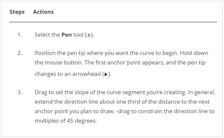
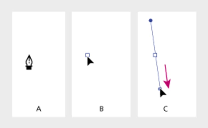
A. Positioning Pen tool
B. Starting to drag (mouse button pressed)
C. Dragging to extend direction lines
1. Release the mouse button, but note that the first segment will not be visible until you draw the second anchor point.
2. Position the Pen tool where you want the curve segment to end, and then do one of the following:
- To create a C-shaped curve, drag in a direction opposite to the previous direction line.
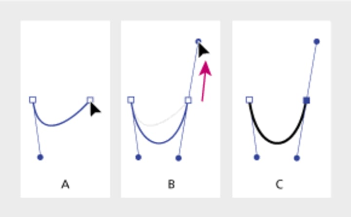
A. Starting to drag second smooth point
B. Dragging away from previous direction line, creating a C curve
C. Result after releasing mouse button
- To create an S-shaped curve, drag in the same direction as the previous direction line.
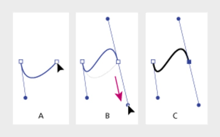
A. Starting to drag new smooth point
B. Dragging in same -direction as previous direction line, creating an S curve
C. The result after releasing the mouse button
1. Continue dragging the Pen tool from different locations to create additional smooth points.
2. Complete the path by doing one of the following:
- To close the path, position the Pen tool over the first (hollow) anchor point. A small loop appears next to the pen tip when it is positioned correctly. Click or drag to close the path.
- To leave the path open, -click (Windows) or -click (Mac OS) anywhere away from all objects, choose Edit > Deselect All, or select a different tool in the toolbox.
Fixing Your Lines
Often, your lines will not look like you planned. Rather than starting over, just fix your lines as necessary!
Closing Paths
To close a path, use the Pen tool. First select one of the two points you want to join, then select the other point. When you are hovering over the first point, the Pen tool will have a slash next to it. When you are hovering over the second point, it will have an O next to it.
Changing Points
If you wish to change a point from a smooth point to a corner point, just click on the Convert Anchor Point button in the Control palette and click on the point you want changed. Doing so will convert the selected anchor point to the opposite point type.
Adding or Removing Points
To add or remove a point on a path, just select the Pen tool with a plus sign (to add) or minus sign (to subtract) next to it and click where you want the point added or removed.
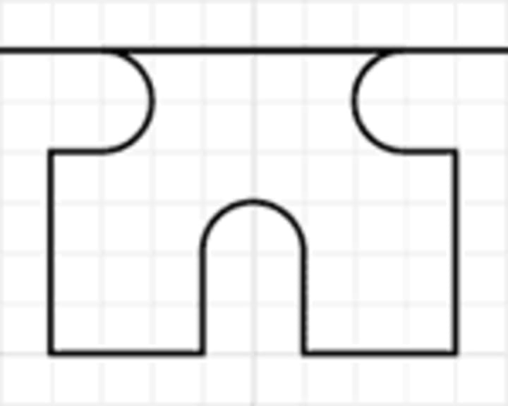
For a challenge, try recreating the following outline using only the Pen tool and the Add Point, Subtract Point, and Convert Point tools mentioned above.
I invite you to try Skillshare Premium for free for 14 days!
There are over 34,000 lessons, taught by creatives from all over the world for free. There are no obligations. You can cancel at any time. Try it now
Working with Type
Getting to Know the Text
In this lesson, you will doing a variety of exercises to gain familiarity with Illustrator’s text functions.
Illustrator’s Text tools are fairly straightforward to use, but can sometimes be confusing to work with. But by using all of the tools Illustrator has to offer, managing and creating your work can be simplified.
This exercise will cover the Type tool, Area Type tool, and Path Type tool. The three vertical variations of these tools won’t be covered because the only difference is the orientation of text.
Preparation
1. Create a new document, landscape orientation.
2. Next, enable the grid (View > Show Grid) and Snap to Grid (View > Snap to Grid).
A few things to keep in mind when using and manipulating type:
- The Selection and Direct Selection tools select the whole object, not a specific section of text, so you should use them to move the entire type object around.
- Use the Type tool if you want to select and edit certain words or letters.
- Use the Character and Paragraph palettes to change a variety of type attributes.
CREATING A CUSTOM TEXT LOGO

- Select the Type tool. Click at the center of the artboard and type “SACG” in capital letters.
- Open the Character palette through choosing either Type > Character or pressing T (PC) or T (Mac).
- Change the font to Arial Black, Italic
- Change the size to 150 points
- Change the tracking (spacing between letters) to -175
After giving the text those attributes, it looks better, but we’re still not satisfied with the way it looks.
3. Text must be converted to outlines before its shape can be edited. Once your text is converted to outlines, the Type tool and Character and Paragraph palettes can no longer edit the appearance, however, because it is now treated as a normal object composed of paths and anchor points.
- Select the type object.
- Right-click on the type object and select Create Outlines from the context menu. You should now be able to see the actual path shapes rather than just a bounding box when selecting the object.
4. We don’t like the way the ends of the “S” angle. Same with the “C” and “G,” so we’ll straighten them out now.
- Examine the picture below.
- Zoom in on one end of the “S.”
- Select the Direct Selection Tool.
- Select the two anchor points, right-click, and select Average Object > Path > Average (J).
- Choose Horizontal and click on OK. This should straighten the end. If you get weird results, undo your action (Z), and make sure that you select the anchor points closest to the end.
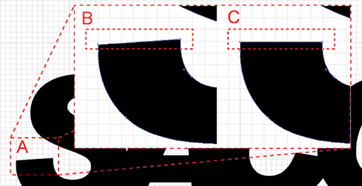
A. Zoomed image.
B. Two anchor points selected using the Direct Selection tool.
C. Result after the Horizontal Average action.
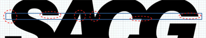
5. Follow the same procedure for the areas highlighted in the picture below. Remember to select only two anchor points at a time! For the letter “C,” use the Lasso Tool (Q) to keep from selecting parts of the letter “G,” and select one anchor point a time, holding down the key to select the second anchor point.
Image for post
6. The logo still needs a little work:
- Select all the letters.
- Unite their paths using the Pathfinder palette (the letters were previously individual shapes that were grouped together).
- Next, create a rectangle similar to the one shown, making sure it covers the highlighted areas.
- Subtract the rectangle from the “SACG” shape:

MORE EFFECTS
There are many more things you can do. Try to remove the bump between the “S” and “A,” or try to remove the notch between the “A” and “C” using the Pen tools. Change the color, or add other objects. Once you convert a text object into an outline, you can manipulate almost anything.

Creating Type that Conforms to Paths or Shapes
- Create shape of desired path or object.
- Select the Path Type tool.
- Pay attention! The object you want type to conform to will disappear, so if you want to preserve it, copy it now!
- Click on the object’s path or outline. Do not click inside or outside the object or you will just create normal text.
- Type in your desired text.
Text conforming to curved path:
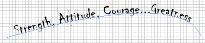
Everything about the object is still editable, from the text to the path. If you want to edit the text, use the Type tool as normal. If you want to edit the curve, use the Direct Selection tool as normal.
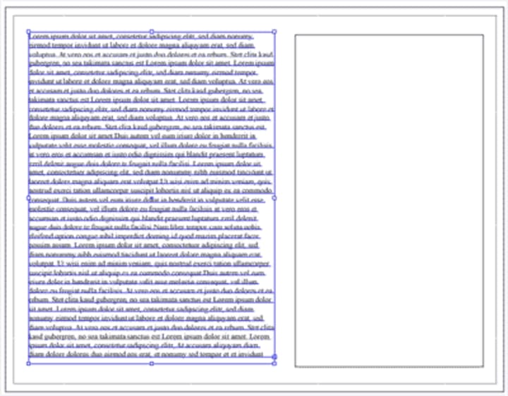
AREA TYPE AND TEXT BLOCKS
- Create two rectangles with heights that span the height of the page. Move them so there’s space between them.
- The object you want type to constrain to will disappear, so if you want to preserve it, copy it now.
- Select the Area Type tool.
- Click on the object’s outline. Do not click inside or outside of the object or you will just create normal text.
- Type, or copy and paste, more text than the shape can fit. An Overflow icon will appear at the bottom right of the shape.
- Select both the text object and the other rectangle.
- Select Type > Blocks > Link. The text should then flow into the the other rectangle.
Text constrained to a rectangle
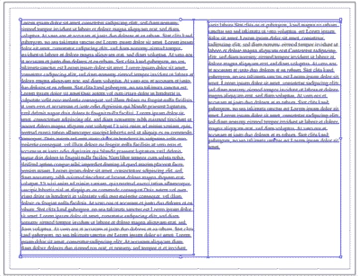
Text flowing into another rectangle
You can link text to other shapes beyond just rectangles: any shape object can have text constrained to it.
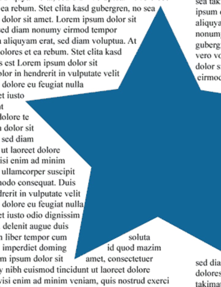
TEXT WRAPPING
You can also make the text conform to shapes within text blocks.
- Create a shape and move it over the text.
- Select the text block and your shape.
- Select Type > Wrap > Make. The text should wrap around the shape as shown in the example.
You can move this shape later using the Direct Selection tool.
I invite you to try Skillshare Premium for free for 14 days!
There are over 34,000 lessons, taught by creatives from all over the world for free. There are no obligations. You can cancel at any time. Try it now
Create a Batman Logo
Objective
- To create a fairly complex object from simple shapes such as circles, rectangles, and polygons.
- To learn to use the Pathfinder palette to create advanced shapes.
- To gain familiarity creating, manipulating, and combining shapes.
- To gain familiarity selecting and moving objects.

In this lesson, you will be creating a bat logo from simple shapes and basic Illustrator commands. There are many different ways to accomplish the same task. As you get more comfortable with Illustrator, you may develop a certain style through either menus or shortcut keys.
Complex objects are often composed of less complex shapes. Although the bat logo isn’t very complex, the process of creating it can be applied to other objects. When creating objects, analyze the structure, look for basic shapes, and tackle one section at a time.
First, enable the grid, if it isn’t already: View > Show Grid, ‘ (Windows) or‘ (Mac OS). Showing the grid by itself does us no good, so select View > Snap To Grid, ‘ (Windows) or <Shift>’ (Mac OS). This “snaps” objects, points, lines, etc., to the grid. It also makes it easier to align objects as well as to make “perfect” and proportional shapes.
Note: You can change the grid size by selecting Edit > Preferences > Guides & Grid….
- Steps Actions
- Select the Ellipse tool (L) and click on the artboard. Use “350 pt” for the width and “150 pt” for the height, and click OK.
- Select black as the fill color in the Color Picker, and the ellipse should turn black.
- Use the Direct Selection tool (A) to select the right half of the ellipse by drawing a box that intersects with the top and the bottom of the right side of the ellipse. Press to delete the right half of the ellipse.
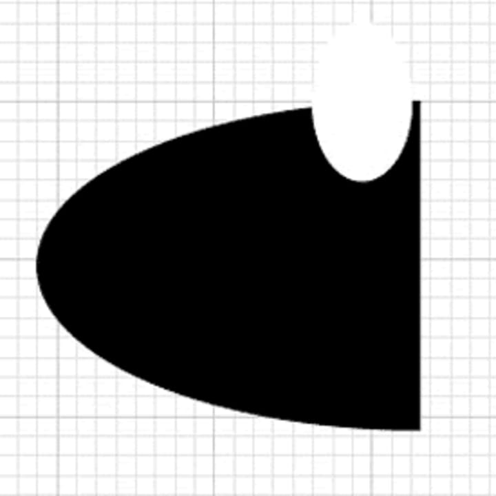
- Select the Ellipse tool again and draw another, smaller, ellipse on the artboard by clicking and dragging the mouse. Give the new ellipse a white fill and stroke color, so that it looks like the ellipse in the first example picture.
- Use the Selection tool (V) to select the white ellipse. Without clicking the mouse, slowly move the mouse cursor outside of the selected ellipse and towards the upper-left corner until the cursor changes to look like a curved arrow. Slightly rotate the ellipse to the left by clicking the mouse and dragging to the left.
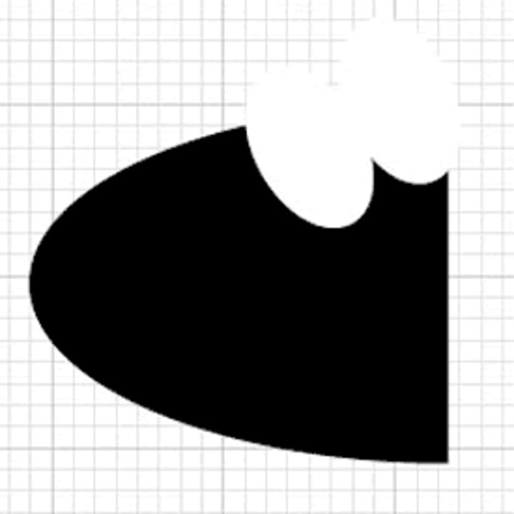
- Copy and paste the white ellipse so that you have two white ellipses. Move the second ellipse with the Selection tool so that the two white ellipses slightly overlap.
- Copy and paste the white ellipse two more times to make a total of four white ellipses. Note that Illustrator always pastes objects in exactly the same spot, so your two pasted ellipses will be directly over one another.
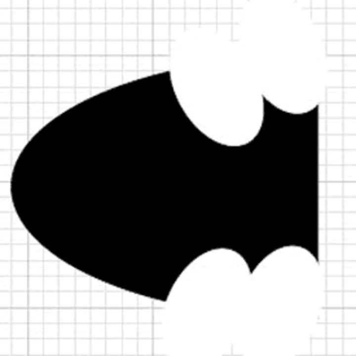
- Arrange the two new white ellipses as shown in the third picture of the example. Using the Selection tool, move them to the bottom half of the black half-ellipse, and this time rotate the bottom left corners slightly to the left.
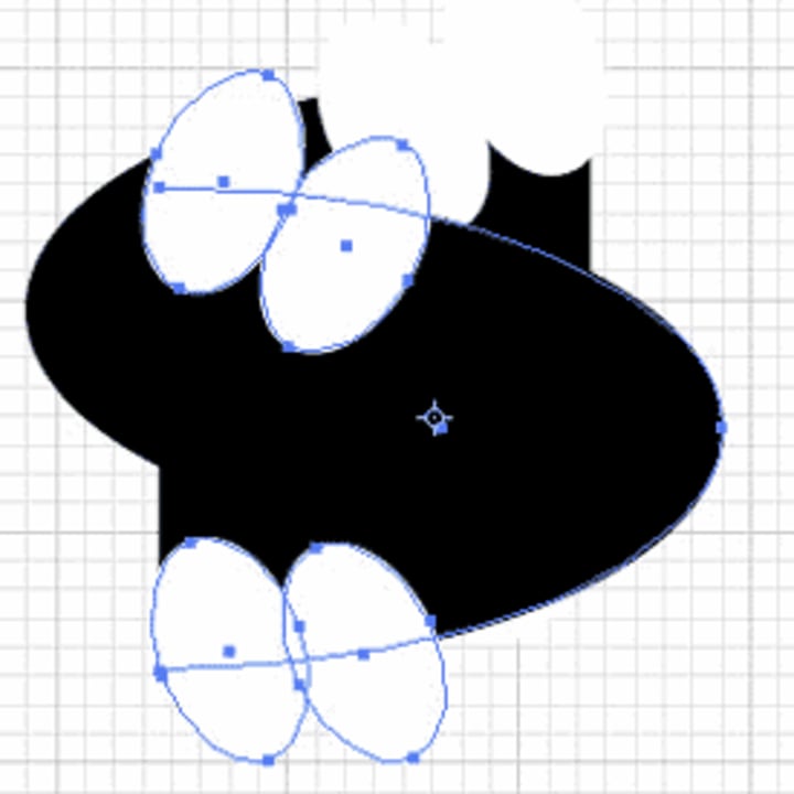
- Use the Direct Selection tool to select the entire object by drawing a box around it. Then copy and paste the entire object so that there are two halves of the bat.
- Hold the mouse down on the Rotate tool icon in the toolbox to be able to select the Reflection tool (O). Press , and the Reflect dialog should appear. Choose a 90 degree reflection along the vertical axis, and click OK. You should now have two bat-halves, each facing an opposite direction.
- Select Window > Pathfinder. Merge all of the shapes in the right-hand bat half selecting the four white ellipses and the large black ellipse (hold down and select each one in turn with the mouse) and then click the Merge button on the Pathfinder palette. Illustrator will now recognize this half as one single object. Click on any section, and see how the entire object is selected instead of the individual ellipse.
- Move the right half of the bat out of the way using the Selection tool, and repeat the step above for the left half.
- Line up the two halves so that they form the bat logo. Select both objects by holding down the as you click on them. In the Pathfinder palette, select the Align tab and click the Vertical Align Center.
- Once the objects are aligned vertically, deselect the View > Hide Grid > Snap to Grid option. Then use select only the right half of the bat and use the arrow keys move it until it joins with the left half.
- The logo looks done, but Illustrator still does not recognize it as one object. Try moving it around or applying a style to it, and you will see that it does not keep the bat shape. To fix this problem, first ungroup the objects by selecting Edit > Ungroup. Each ellipse should now be selectable as its own object.
- Select all of the white ellipses by holding down the key as you click on them. On the Pathfinder tab, click Subtract from shape area. Then select both black halves and use the Merge button again.
- Done!
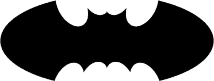
Using simple shapes, commands such as Rotate, and the Pathfinder and Align palettes, we are able to create a fairly complex object.
Remember, similar concepts can be applied to other complex objects! Analyze the object, look for simple shapes, and work on one section at a time.
I invite you to try Skillshare Premium for free for 14 days!
There are over 34,000 lessons, taught by creatives from all over the world for free. There are no obligations. You can cancel at any time. Try it now
Creating a Key Logo
Objectives
- To create a fairly complex object from simple shapes such as circles, rectangles, and polygons.
- To learn to use the Pathfinder palette to create advanced shapes.
- To gain familiarity creating, manipulating, and combining shapes.
- To gain familiarity selecting and moving objects.

In this lesson, you will be creating the Key Bank logo from simple shapes and basic Illustrator commands. There are many different ways to accomplish the same task. As you get more comfortable with Illustrator, you may develop a certain style through either menus or shortcut keys.
Complex objects are often composed of less complex shapes. Although the Key Bank logo isn’t very complex, the process of creating it can be applied to other objects. When creating objects, analyze the structure, look for basic shapes, and tackle one section at a time.
First, enable the grid, if it isn’t already: View > Show Grid (‘). Just showing the grid does us no good, so select View > Snap To Grid (‘). This “snaps” objects, points, lines, etc., to the gridlines. It also makes it easier to align objects and make “perfect” and proportional shapes.
Note: You can change the grid size by selecting Edit > Preferences > Guides & Grid….
PART A: Creating a key handle
- StepsActions
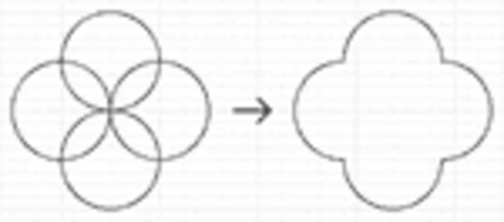
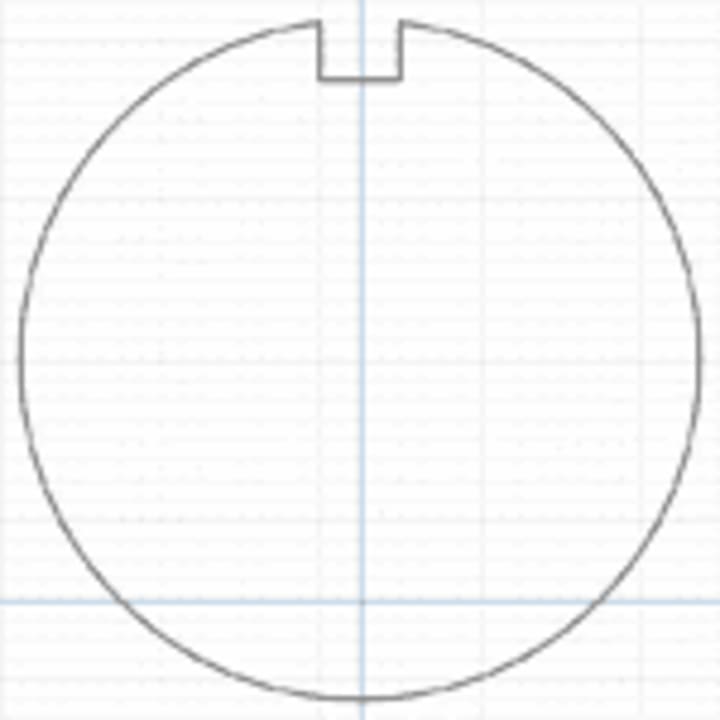
- Select the Ellipse tool (L) and click on the artboard. Use “1” for both width and height, and click OK.
- Copy and paste the circle three times to make a total of four circles. Note that Illustrator always pastes objects in exactly the same spot, so your circles will be directly over one another.
- Arrange the circles as shown in the picture. Select the objects and set the fill color to transparent to see the shape outlines.
- Open the Pathfinder palette (Window > Show Pathfinder (F9). Select all four circles and click the Merge button in the Pathfinder palette.
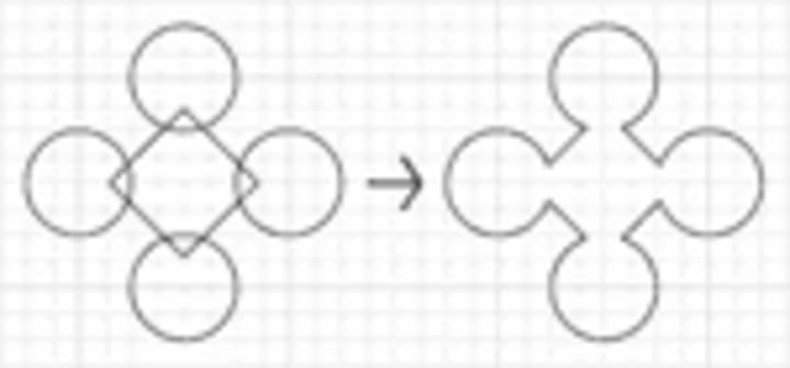
- Create four circles half an inch in diameter, and a five inch wide square, using the Ellipse and Rectangle tools.
- Select the square and double-click on the Rotate tool (R) in the toolbar. This brings up the Rotate dialog. Check the Preview and set the Angle to 45 degrees. Then arrange the circles at the corners of the diamond as shown in the example. Select these five shapes and use the Merge button to merge them.
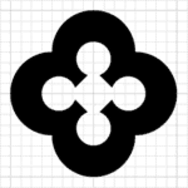
- Select the two remaining shapes and use the Horizontal Align Center and Vertical Align Center buttons in the Align tab of the Pathfinder palette. Reduce the size of the inner shape by scaling (Object > Transform > Scale…) it.
- Select the two shapes and use the Minus Front button in the Pathfinder palette (if you get an error message, use Minus Back instead). The result of the Minus Front action isn’t evident if the object has no fill color. Change the fill color and you should see that the inner shape has become a “hole.”
PART B: Creating a key shaft and handle
- StepsActions
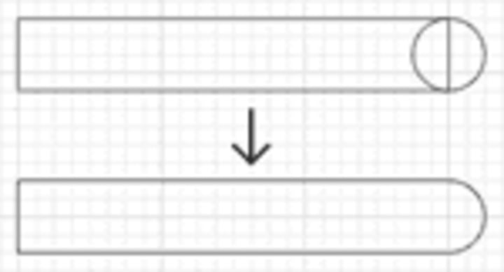
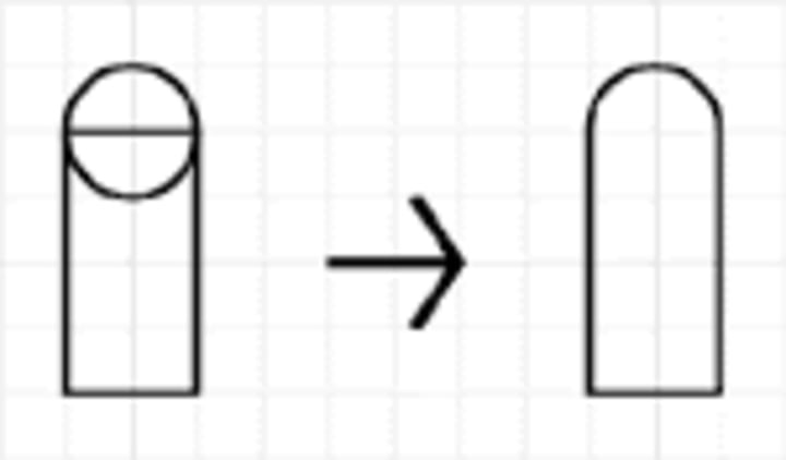
- Create a rectangle three inches wide and half an inch high. Create a circle half an inch in diameter. Position them as shown in the example and use the Pathfinder palette to merge them.
- Position the shaft over the handle if necessary and merge the two shapes.
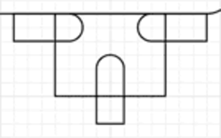
- Create a rectangle one inch wide and three quarters of an inch high and position it under the right side of the shaft.
- Create a circle a quarter inch in diameter. Create a rectangle a quarter inch wide and half an inch high. Position them as shown and merge them.
- Copy and paste the shape twice. Rotate one 90 degrees counterclockwise and the other clockwise. Position them over the rectangle as shown.
- Select the three smaller shapes and merge them. The three objects are now treated as one and we can now subtract them from the rectangle.
- Select the rectangle and three-part object and use the Minus Front button.
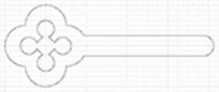
The Finished Product

Merge the teeth shape with the handle and shaft, change the fill color to red and stroke color to none, and the key is finished.
Using simple shapes, commands such as Rotate, and the Pathfinder and Align palettes, we are able to create a fairly complex object.
Remember, similar concepts can be applied to other complex objects! Analyze the object, look for simple shapes, and work on one section at a time.
Key Bank logo © Key Bank, yadda yadda yadda ; and this isn’t necessarily the way they made it, we think.
I invite you to try Skillshare Premium for free for 14 days!
There are over 34,000 lessons, taught by creatives from all over the world for free. There are no obligations. You can cancel at any time. Try it now
Creating a Biohazard Symbol
Objectives
- To create a fairly complex object from simple shapes such as circles, rectangles, and polygons.
- To learn to use the Pathfinder palette to create advanced shapes.
- To gain familiarity creating, manipulating, and combining shapes.
- To gain familiarity selecting and moving objects.

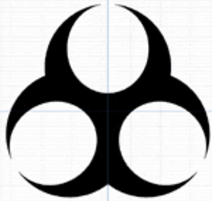
In this lesson, you will be creating a biohazard symbol using concepts from the previous tutorials.
As stated in earlier tutorials, complex objects are usually composed of less complex shapes. Although a biohazard symbol is a bit more complex than the objects created in previous tutorials, the process of creating the previous shapes can be applied to this object (and others). Just remember: when creating objects, analyze the structure, look for basic shapes, and tackle one section at a time. We’ve made some shapes to save time, but you may want to study the basic shapes first.
First, download and open biohazard.ai. You should see many different shapes in separate layers. Next, enable the grid (View > Show Grid), Snap To Grid (View > Snap to Grid), and Guides (View > Guides > Show Guides) if they aren’t enabled already. You can look at the different shapes on the different layers by clicking on the Eye icon (
Image for post
) next to a layer in the Layers palette. When you are ready to begin, turn off the visibility by clicking on the Eye icon for all the layers, except the “Guides” layer and “Layer 2.”
- Steps Actions
- 1. Select the large circle and rectangle shapes in Layer 2. Subtract the rectangle from the circle using the Pathfinder palette tools.
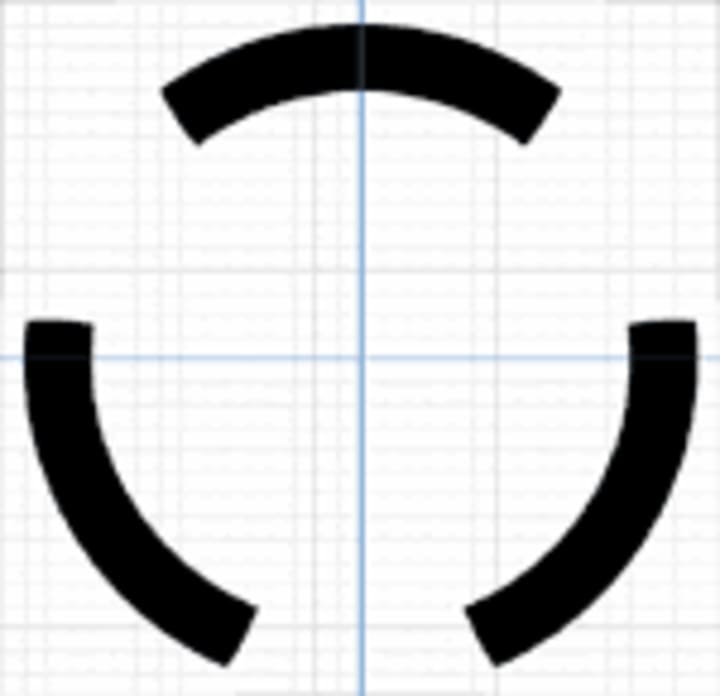
- 2. Select the merged shape. Choose the Rotate tool (R) and hold down the key while you click where the two guides intersect. This does two things: a) it moves the pivot point to where you clicked, and b) brings up the Rotate dialog for you to enter a specific rotation degree and preview settings changes. Check the Preview box, and enter 120 as the Angle. Click Copy to make a rotated copy of the original shape.
- 3. You can rotate the second shape using the same procedure above, or simply use Object > Transform > Transform Again (D (Windows) orD (Mac OS)). Then select the notched circles and merge them.
- 4. Make Layer 3 visible. Rotate and copy Layer 3’s ellipse using the same techniques outlined above. Then merge the three ellipses using the Pathfinder palette. Be careful not to select the larger shape from Layer 2! locking or hiding Layer 2 will help keep you from selecting anything on it.
- 5. Subtract the three inner ellipses in Layer 3 from the larger shape on Layer 2. You should now be able to see a general biohazard shape.
- 6. On Layer 4, subtract the small circle from the larger shape. On Layer 5, rotate and copy the rectangle. Merge the two rectangles, and subtract them from the emerging biohazard shape.
- 7. On Layer 6, select the two circles. Right-click on the artboard and select Make Compound Path from the context menu to make a doughnut-shaped object (subtracting the smaller circle from the larger circle would accomplish the same thing).
- 8. Also on Layer 6, select the ellipse. Hold down the and keys, and scale the ellipse a little smaller (holding down constrains it to a center point and holding down constrains the proportions).
- 9. Select the ellipse and doughnut shape. Click on the Intersect shape areas in the Pathfinder palette. Rotate and copy the resulting shape.
- 10. Finally, select all of the shapes and merge them.
I invite you to try Skillshare Premium for free for 14 days!
There are over 34,000 lessons, taught by creatives from all over the world for free. There are no obligations. You can cancel at any time. Try it now
About the Creator
Keep reading
More stories from free businees and writers in Lifehack and other communities.
PUBG Mobile 2021 Global update
PUBG Mobile Lite 0.20.1 Global update (Season 21 WP): APK download link for worldwide users PUBG Mobile Lite is the streamlined version of the famous battle royale title — PUBG Mobile. It is made explicitly for users with low-end devices and has garnered a massive player base across the world.
By free businees5 years ago in Gamers


Comments
There are no comments for this story
Be the first to respond and start the conversation.