Latest Stories
Most recently published stories in History.
Nikola Tesla's Life
Nikola Tesla, born on July 10, 1856, and died on January 7, 1943, was a Serbian-American inventor, electrical engineer, mechanical engineer, and futurist. He is best known for his significant contributions to the development of the modern alternating current (AC) electricity supply system.
By Arjin Arık3 years ago in History
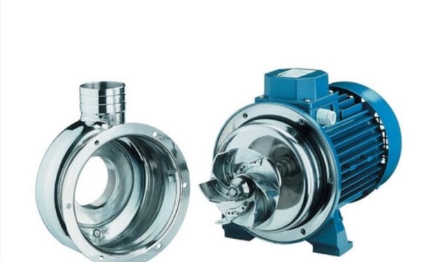
How pump works
A detailed understanding of the design principles behind centrifugal pumps is not essential to this book, though a grasp of the fundamentals is. Real Impellers have a series of blades attached to a rotating disk. The blades normally slope backward, away from the direction of rotation. As the impeller rotates, the curvature of the blade pushes the liquid out into the casing that surrounds it. This collects the displaced fluid and directs it into the piping. These are called centrifugal pumps. The centrifugal force arises because the radius at which an individual particle leaves the impeller is larger than that at which it enters. As liquid is displaced out into the casing, more liquid is pushed in to replace it.1 This process takes place continuously to create a pumping action. Basic elements of a single stage centrifugal pump. Impeller [here with seven vanes] and single volute collector One member of the pump family displaces the liquid axially. These impellers look more like propellers, a name which is probably more apt. The force that displaces the liquid is only due to the hydrodynamic vane action. Here, liquid leaves the propeller at more or less the same radius as it enters, so there can be no centrifugal forces involved. In all but the pure axial flow impeller, head is being generated by both centrifugal force and vane action. At the axial flow end of the family almost all theCentrifugal pumps are the most preferred pumping devices in the hydraulic world. In this article we will have a conceptual overview of working of centrifugal pumps. At the heart of the system lies the impeller. It has got a series of curved vanes, fitted inside shroud plates. The impeller is always immersed in water. When the impeller is made to rotate, it makes the fluid surrounding it also rotate. This imparts centrifugal force to the water particles and the water moves radially out. Since rotational mechanical energy is transferred to the fluid, at discharge side of the impeller, both pressure and kinetic energy water will rise. At the suction side water is getting displaced, so a negative pressure will be induced at the eye. Such a low pressure helps in sucking freshwater stream into the system again. and this process continues. This is the reason why priming is important for centrifugal pumps. If no water is present initially. the negative pressure developed by the rotating air at the Eye of impeller will be negligibly small to suck fresh stream of water. Impeller is fitted inside a casing. So the water moving out will be collected inside it, and will move in the same direction of rotation of impeller, to the discharge nozzle. Here you can note one speciality of casing. It has got increasing area along the flow direction. Such increasing area will help in accommodating, newly added water stream and will also help in reducing exit flow velocity. Reduction in flow velocity will result in increase in static pressure, which is required to overcome resistance of pumping system Here you can see more details of veins inside impeller. They are backward curved vanes with state-of-the-art Eye configuration. If pressure at suction side impeller goes below vapor pressure of water, a dangerous phenomenon could happen. Water will start to boil forming vapor bubbles and spoil impeller materials over time This phenomenon is known as cavitation. More the section head, lesser should be the pressure at the suction side, to lift the water. This fact puts a limit to maximum suction head a pump can have. Careful pump selection is required to avoid the problem of cavitation. The current impeller type is enclosed, semi-open and open impellers are also in use depending upon the application. If the working fluid is cloggy in nature, it is preferred to use open kind of impeller. But they are slightly less efficient. Mechanical design of centrifugal pump is always challenging. A shaft is used to connect between the impeller and motor Since water pressure inside the casing is huge, a proper sealing arrangement is imperative in arresting water leakage through the shaft-casing clearance. Mechanical seal or stuffing box based mechanism is used for this purpose. Impeller is mounted on bearings, but at the suction side impeller, it is not advisable to fit a bearing, since it will block the flow. So bearings have to be fitted at the other end. This means impeller is mounted like a cantilever. For high flow rate pumps, a bearing housing with cooling oil is necessary for improving the life for bearings.head is generated by vane action. At the centrifugal flow end, most, but not all, of the head comes from centrifugal force. In between these two extremes are the impellers known as mixed flow. Here the head from the vane action and centrifugal contributions are comparable. The centrifugal pump is by far the most prolific member of the pump family, so it is most useful to concentrate on these. How does a centrifugal impeller work? One simple mental experiment can demonstrate the principle upon which centrifugal pumps are based. 9 Imagine an open bucket, half-filled with water, and suspended on the end of a short piece of rope, m Next, imagine swinging that rope around in a vertical plane. The centrifugal forces acting on the water keep it in place inside the bucket. It does not fall out as long as the bucket is being swung fast enough. The centrifugal force pushes the water into the bottom of the bucket, even when it is upside down. The centrifugal force pressurises the liquid in the bucket. The faster the bucket spins the greater the centrifugal force and the greater the liquid in the base of the bucket is pressurised. In other words, the liquid tries to push the base off the bucket. What would happen if there were small holes in the base of the bucket? Well, the centrifugal force would continuously push liquid out of the bucket, Each particle of water is thrown off the bucket- impeller at a tangent, just as do particles flung off from a wet spinning bicycle wheel. The casing would then normally direct the particles into a pipe, or, for illustration, into a fountain. The faster the particles are flung off, the higher the casing can direct itas a fountain. Bigger impellers fling particles faster and hence higher than small impellers running at the same speed. On the other hand spinning the impeller faster will do the same thing. It simply remains to provide a continuous feed to the bucket and all the elements of a centrifugal pump are in place for this mental experiment. Most centrifugal pumps are purchased to stimulate flow. In the process, they also pressurise the liquid. This pressurisation is useful in overcoming any resistance to flow. Finding the correct combination is the task of the pump designer. A minority of pumps are purchased to pressurise a process, and here any flow is largely incidental. In any event, the relationship between pump flow and pump generated head/pressure is a very important one and must be known in order to ensure good pump scheme flowknown as the pump characteristic curve, the pump performance curve, or mostly, 'the curve'. This is basically, what manufacturers do on their test bed, in order to determine the pump performance curve. [though they use different techniques] The curve derived from this method will generally steadily fall to the right. In some rarer cases, the curve may show a point of discontinuity at Range of curve shapes likely to be about 40 to 70% of the pump encountered design flow. This is typical of very high flow- low head pumps. Operation below the point of discontinuity is possible, but generally discouraged since it will be associated with unsatisfactory pump running. In general operation of ANY pump at low flow is to be discouraged, though more common pumps would not have such a restrictive level as 70%. Occasionally pumps appear with characteristics that do not steadily fall to the right. Although there is widely held negative view of such curves, they are really only of consequence if the pump has to operate in parallel with another, or the static head is unusually high. Pumps with this sort of characteristic are physically smaller than a pump with a steadily falling curve, As a result, they may find favour in applications where space is at a premium, and the two mentioned constraints do not apply. Mine dewatering is a typical case. Pump head and pressure Pump engineers often interchange the words pressure and head when discussing pump performance. Pump head is a constant property, while pump pressure depends upon the liquid specific gravity, Important as the performance curve is, other associated data is taken to give a more complete picture of the pumps behaviour characteristics. This data should be taken almost simultaneously with the curve data.Impeller fundametals There are of course many nuances to the geometry of a pump impeller, most of which arc only of real interest to the designer. To the pump owner/user three parameters need to be understood, 9 Eye diameter, DI: In con- junction with the pump speed, the eye diameter will largely Three main impeller design decide how much flow the parameters pump can accept, as well as the minimum suction pressure requirements to avoid cavitation. Increasing D 1 allows the impeller to accept more flow. Alternatively, without increasing the flow, an increase in D1 [Up to a point] reduces the minimum suction pressure requirements. When D1 approaches D2, there is too little radial space to install efficient vanes. Such extreme designs might be associated with operation 'bad habits' 9 Impeller outlet diameter, D2: In conjunction with the pump speed, the outlet diameter will largely dictate how much head the pump generates. Increasing D2 will also increase the pump head/pressure, and vice versa 9 Impeller outlet width, b2: In conjunction with pump speed, this will decide how much flow the pump can discharge. In combination with D2 this will also decide the slope of the Flow-Head curve and the shape of the Flow-power curve. Generally enclosed impellers where b2 is less than 2% of D2 are quite difficult to manufacture. At this level it is sufficient to note, without further discussion, that the geometry of the stationary casing components can also play a role in pump performance. However, the three items referred to above are the most critical in terms of achieving, and maintaining performance. In that respect, it is worth recording these dimensions whenever a pump is dismantled, and verifying them if ever replacement spare parts are ordered. Manufacturers often have a range of different impellers for the same pump casing, and occasionally supply errors occur. These can easily be avoided by keeping a record of these check dimensions. Other data worth recording is the number of impeller vanes.Basic impeller Designers call this basic impeller a single stage -single entry impeller. This single impeller will have a certain characteristic curve, depending upon its geometry, Performance of a pump with a single basic impeller. This basic impeller has only one "eye", or entry annulus Using this basic impeller as a benchmark, flow can be increased simply by increasing D1, & b2. At some point, D1 approaches D2, with the result that there is barely enough radial space for the vanes to do work on the liquid. Impellers that approach this limit often have 'bad habits' associated with them. For example their band of useful operation might be quite limited, and they are susceptible to hydraulically excited vibrationOf course a single impeller may be operated at an increased speed, and this may result in more flow, see Appendix C. But in doing this, the suction pressure requirements of the pump also increase. With a fixed level of sitc suction pressure, there will be limits to which the speed can be increased-even if the pump is capable of it. In these cases it is necessary to conceptually combine two impellers so that they operate in parallel. Such impellers are lmown as double entry designs, because they have two 'eyes'. This concept is described next. Impellers in parallel- more flow In this case, 2 single stage impellers are arranged back to back, and in parallel. This doubles the pump flow but the head stays the same. These are known as double-entry single stage designs. Sometimes the pump does actually use two separate impellers, but more usually they are manufactured as a single entity, Their main purpose is to increase the flow limitations of single entry designs. A side benefit is that, at the same flow, double entry impellers would normally require less suction pressure than impellers of single entry because the flow per eye has been halved.
By Habib Ur Rehman3 years ago in History
Unsolved Mysteries of the World and the Universe That Defy Explanation...
Welcome back to another adventure as we explore ten fascinating mysteries of the world and the universe. Get ready to be amazed and enthralled as we learn the answers to questions that have perplexed historians, scientists, and astronomers alike. These are some of our favourite topics to discuss, and if you have any requests for future ones, just let us know in the comments below.
By Francis Dami3 years ago in History
Unraveling the Secrets of Egypt"
In the heart of the desert, where the sand dunes stretched endlessly and whispered tales of ancient civilizations, lay the mysterious land of Egypt. Its pyramids, pharaohs, and hidden tombs held the secrets of a glorious past, waiting to be discovered by those with an insatiable thirst for knowledge and adventure.
By Arslan Mirza3 years ago in History
"A Daring Escape: The Courageous Journey of Lieutenant Anderson"
In the heart of World War II, when the world was consumed by chaos and despair, a story of unwavering bravery and indomitable spirit unfolded. It is the remarkable tale of Lieutenant Anderson, a captured Allied soldier who embarked on a daring escape, defying all odds and leaving an indelible mark on the annals of history.
By arsal sial3 years ago in History
Time Traveling Through Occupations
If I were born in a different historical period, my occupation would be vastly different from what I have today. The job market, technology, and societal norms have evolved significantly over the years, and it is intriguing to consider what I would have done for a living in the past.
By Lionel Tchami3 years ago in History
Reviewing "The 40 Rules of Love" by Elif Shafak
Introduction In this article, I will be reviewing the book "The 40 Rules of Love" by Elif Shafak, which is the first book in a series of reviews on books by Turkish authors. As an avid reader, I recently finished reading this book and would like to share my opinion with you. Elif Shafak is a renowned Turkish author, and this international bestseller intrigued me as it was my first introduction to Turkish literature.
By Tajamul Hassan3 years ago in History
Viking Exploration And Navigation Techniques
The Vikings were renowned seafarers, known for their audacious explorations and exceptional navigational skills. In the following article, we will delve deep into the details of their exploration and navigation techniques, delving into the historical context, ship designs, navigation methods, and their impact on global history.
By Vikings Rule3 years ago in History