

Clap switch circuit is basically a sound detector which detects sound and converts that sound energy into some electric pulses. The condenser mic is one of the main components in the circuit that tracks the input clap sound based on the pitch of clap and transduces this sound energy into some electric pulses.
Introduction :
A circuit which operates through clap sound otherwise similar to that sound is called clap switch. This circuit is used to make the light ON through a clap sound, but it can work through any kind of same pitch sound. The essential components used to build this project are electric condenser mic as a sound sensor. The main function of this device is to change the energy of sound to electrical. We can make a clap switch circuit by using different parameters but here my aim is to assemble a mini project on the breadboard using some basic components. This project has many advantages like automatically controlling lights within a specified range by clapping action, it is an advantageous technology for mobility-impaired persons, it is reliable, its cost is low, and it provides good output efficiency. Clap Switch is not restricted to turning the LEDs ON and OFF, but it can be used in any electric appliances such as Tube Light, Fan, Radio, or any other basic circuit which you want to turn ON by a Sound. This working of this circuit is based on amplifying nature of the transistor, the switching nature of transistor, electronic switch. Basically, this is a Sound operated switch.
The most crucial element in this circuit is a condenser microphone since it will detect sound and transform that energy. A capacitor, sometimes known as a condenser, is an electronic component used to store electrical energy as an electrostatic field. The condenser microphone, as its name implies, transforms sound (pressure fluctuations) into electrical impulses using a capacitor. Thus, it is also referred to as an electrostatic microphone. A transistor may use a little signal between one pair of its terminals to control a much bigger signal at another pair, thus the microphone will transmit a signal to the LED, and we would use that signal to magnify the sound. The output terminal would be a collector and then the output can be predicted by LED, but the LED would blink for very little time in order to increase that timing a 555 timer IC chip would be used. The main goal behind making this project is that we can help people through this project, especially handicapped people and we can produce electric pulses through sound which can be used to generate more electricity. Plus the cost is low so the economy can be affected by this.
Literature Review:
The operation of almost every electronic devices is concerned with electrical signals that can be either ON or OFF. Thus, switches are essential to the operation of electronic circuits and is only operational in either an ON or an OFF state. They are important in engineering, since they are utilized in a great variety of machines and electronic circuits upon which today's industrial technology are based. A clap light switch is a circuit that light a bulb when sound is produced either by a claps of hand or by a car horns. The operation of a clap light switch is a digital circuit because of its binary “ON” state and “OFF” state. A clap switch free from triggering turn ON/OFF any clapping. The sound energy produced is transformed by the circuit to electrical energy and its final output state changes to light energy. Basically a clap switch circuit plays important role in home automation because if we increase the frequency or range of microphone it can detect sound from very far range also .
Required Components
• Breadboard
• Condenser mic (Capacitance range(5 to 100Pf))
• Resistors (1 kΩ , 3.3 kΩ , 270 Ω)
• LED
• IC Chip (555 timer)
• n-p-n transistor (BC-547)
• Capacitors (22 micro F , 100 nano F)
• Battery (5-6 volt)
• Condenser Mic :
Condenser here refers to a capacitor, an electronic part that stores electrical energy as an electrostatic field. The condenser microphone, as its name suggests, converts sound (pressure fluctuations) to electrical impulses using a capacitor. Consequently, it is also known as an electrostatic microphone. We are all aware that when two parallel plate conductors are separated by a certain amount, a capacitance will result. The capacitance produced will be directly proportional to the plate area and inversely proportional to the plate spacing.
• 555 Timer IC :
In order to increase the duration of blinking 555 timer IC chip is used. The 555 timer IC is basically an integrated circuit (chip) used in a variety of timer, delay, pulse generation, and oscillator applications. Derivatives provide two (556) or four (558) timing circuits in one package. The design was first marketed in 1972 by Signetics. Since then, numerous companies have made the original bipolar timers, as well as similar low-power CMOS timers. In 2017, it was said that over a billion 555 timers are produced annually by some estimates, and that the design was "probably the most popular integrated circuit ever made". The internal block diagram and schematic of the 555 timer are highlighted with the same color across all three drawings to clarify how the chip is implemented:
• Voltage divider: Between the positive supply voltage VCC and the ground GND is a voltage divider consisting of three identical resistors (5 kΩ for bipolar timers, 100 kΩ or higher for CMOS) to create reference voltages for the comparators. CONTROL is connected between the upper two resistors, allowing an external voltage to control the reference voltages:
o When CONTROL is not driven, this divider creates an upper reference voltage of 2⁄3 VCC and a lower reference voltage of 1⁄3 VCC.
o When CONTROL is driven, the upper reference voltage will instead be VCONTROL and the lower reference voltage will be 1⁄2 VCONTROL.
• Threshold comparator: The comparator's negative input is connected to voltage divider's upper reference voltage, and the comparator's positive input is connected to THRESHOLD.
• Trigger comparator: The comparator's positive input is connected to voltage divider's lower reference, and the comparator's negative input is connected to TRIGGER.
• Flip-flop: An SR flip-flop stores the state of the timer and is controlled by the two comparators. RESET overrides the other two inputs, thus the flip-flop (and therefore the entire timer) can be reset at any time.
• Output: The output of the flip-flop is followed by an output stage with push–pull (P.P.) output drivers that can supply up to 200 mA for bipolar timers, lower for CMOS timers.
• Discharge: Also, the output of the flip-flop turns on a transistor that connects DISCHARGE to the ground.
• Resistors:
Resistors are the most common passive electronic component (one that does not require power to operate). They are used to control voltages and currents. While a resistor is a very basic component, there are many ways to manufacture them. Each style has its own characteristics that make it desirable in certain types of applications. Choosing the right type of resistor is important to making high-performance or precision circuits work well. This bonus chapter covers the resistor types and helps with picking the right one for your project.
• Capacitors :
Capacitor has ability to store charge and release them later. Capacitance is the measure of the amount of charge that a capacitor can store for a given applied voltage. The unit of capacitance is the farad (F) or microfarad. The capacitors used in the circuit are electrolytic capacitor. In the circuit the electrolytic capacitor is used as a bypass capacitor. Any noise variation in the circuit is removed by the capacitor.
• Voltage Supply :
For this circuit we will give 5 or 6 volts basically according to the supply we will change resistances because due to ohm’s law which is V=IR , the voltage is directly proportional to input or load resistance. The change in voltage will change the resistances also because increasing the resistance value reduces the sensitivity.
VOLTAGE
SUPPLY RESISTORS
USED
• 5-6 volts
270 ohm, 330 ohm, 470 ohm
• 9 volts
470 ohm, 1k ohm
• 12 volts
1k ohm, 1.5k ohm
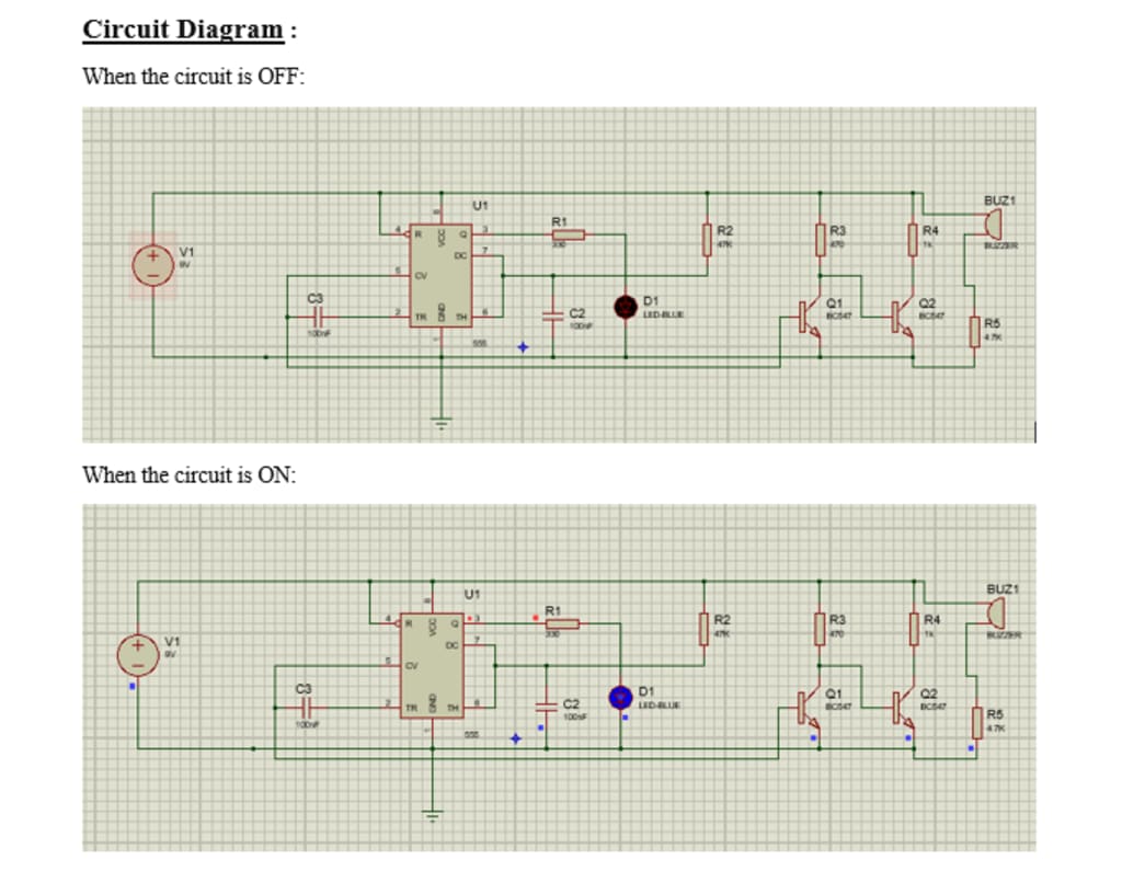
Working :
The sound-activated sensor used to create this circuit (as shown below) senses the sound of a clap as input and processes it in the circuit to produce the output. The Electric Condenser Mic converts sound into electrical energy when it receives sound as input, which causes the LED to illuminate. As soon as we input sound, the LED comes ON, and it automatically turns OFF after a brief period. The 100mF capacitor linked to the 555 timer, whose primary function is to generate the pulse, allows the turn-on LED timer to be adjusted. First, we will plot a primary circuit on the breadboard which will include a condenser mic, resistors, n-p-n transistors, and an LED in order to check the working. We use n-p-n transistors instead of p-n-p transistors because n-p-n transistors have high electron mobility, so it provides more conduction as electrons are majority charge carriers here. Now first we will give a power supply to the primary circuit so that we can check LED is working or not. And then we will assemble the secondary circuit in order to increase the blinking time in which 555 timer IC chip will be used in which capacitors would be connected also.
Even though the circuit is called a "clap switch," you are not required to input data just as claps. This is also known as a "Sound Operated Switch" because it can be any sound with the same pitch as a clap. Because the negative terminal of Mic is linked to the transistor directly, this circuit has primarily relied on transistors. Since there is no electronic switch in this circuit to turn it on or off, when you connect the battery, your circuit is now turned on and is ready to accept inputs in the form of sound energy. This circuit can be changed by utilizing a relay as an electronic switch to turn it ON or OFF. When we apply sound to the circuit, it immediately amplifies the sound signals and sends them to the 555 timer, which creates the pulse that activates the LED. You must ensure that the condenser mic's negative side is connected to the amplifier in order to avoid the circuit heating up and maybe prevent the use of various transistor models, etc.
Conclusion :
Whenever we will blow air on condenser microphone or would speak with a frequency range between 2200 to 2800 hertz the LED connected with it will get on because that condenser mic will detect sound and would convert that energy to light up a bulb. The clap activated switching device function properly by responding to both hand claps at about three to four meter away and finger tap sound at very close range, since both are low frequency sounds and produce the same pulse wave features. The resulting device is realizable, has good reliability and it’s relatively inexpensive. Assemble the circuit on a general-purpose PCB and enclose it in a suitable box. This circuit is very useful in field of electronic circuits. By using some modification, it area of application can be extended in various fields. It can be used to raised alarm in security systems with a noise,and also used at the place where silence needed.
About the Creator
Sana Asif
An electrical engineering student sharing experiences about education, life and university :)
Keep reading
More stories from writers in Education and other communities.
What Caused the Big Bang?
Understanding the Big Bang Theory The Big Bang does not describe an explosion in space. Instead, it describes an expansion of space itself. At the beginning, all matter, energy, space, and time were compressed into an extremely small, hot, and dense state.
By shahkar jalal3 days ago in Education
Eating with Purpose: How Smart Nutrition Transforms Health and Lifestyle
Smart nutrition has emerged as a critical element of modern wellness, emphasizing intentional, balanced, and sustainable dietary choices. Unlike restrictive or fad diets that prioritize short-term results, smart nutrition focuses on long-term health, encouraging a thoughtful approach to the foods we consume daily. By understanding how nutrients affect the body, individuals can enhance energy, optimize performance, and foster mental clarity. This holistic approach reshapes not only physical health but also lifestyle habits, creating meaningful and lasting transformations.
By Matthew Pothoff4 days ago in Education
Instructions Included Challenge Winners
For the Instructions Included challenge, we asked writers to tell a story through instructions and to trust the form to carry what could not be said outright. Across the top entries, that trust paid off in many different ways.
By Vocal Curation Team3 days ago in Resources


Comments
There are no comments for this story
Be the first to respond and start the conversation.