
How centrifugal pump works
Working of Centrifugal Pump
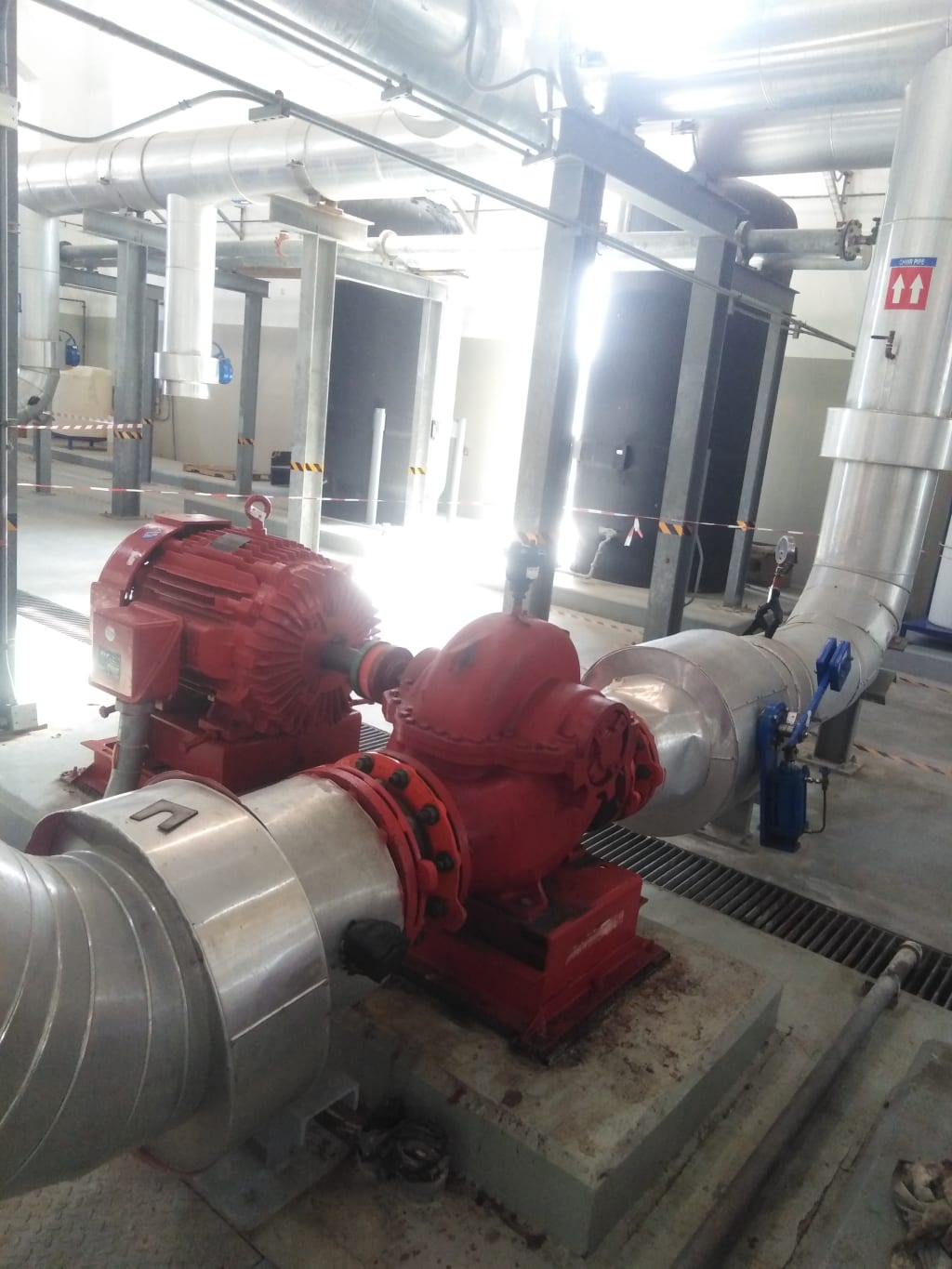
Centrifugal pumps are the most preferred pumping devices in the hydraulic world. In this article we will have a conceptual overview of working of centrifugal pumps. At the heart of the system lies the impeller. It has got a series of curved vanes, fitted inside shroud plates. The impeller is always immersed in water. When the impeller is made to rotate, it makes the fluid surrounding it also rotate. This imparts centrifugal force to the water particles and the water moves radially out. Since rotational mechanical energy is transferred to the fluid, at discharge side of the impeller, both pressure and kinetic energy water will rise. At the suction side water is getting displaced, so a negative pressure will be induced at the eye. Such a low pressure helps in sucking freshwater stream into the system again. and this process continues. This is the reason why priming is important for centrifugal pumps. If no water is present initially. the negative pressure developed by the rotating air at the Eye of impeller will be negligibly small to suck fresh stream of water. Impeller is fitted inside a casing. So the water moving out will be collected inside it, and will move in the same direction of rotation of impeller, to the discharge nozzle. Here you can note one speciality of casing. It has got increasing area along the flow direction. Such increasing area will help in accommodating, newly added water stream and will also help in reducing exit flow velocity. Reduction in flow velocity will result in increase in static pressure, which is required to overcome resistance of pumping system Here you can see more details of veins inside impeller. They are backward curved vanes with state-of-the-art Eye configuration This vane is extracted from a KIRLOSKAR pump model. If pressure at suction side impeller goes below vapor pressure of water, a dangerous phenomenon could happen. Water will start to boil forming vapor bubbles and spoil impeller materials over time This phenomenon is known as cavitation. More the section head, lesser should be the pressure at the suction side, to lift the water. This fact puts a limit to maximum suction head a pump can have. Careful pump selection is required to avoid the problem of cavitation. The current impeller type is enclosed, semi-open and open impellers are also in use depending upon the application. If the working fluid is cloggy in nature, it is preferred to use open kind of impeller. But they are slightly less efficient. Mechanical design of centrifugal pump is always challenging. A shaft is used to connect between the impeller and motor Since water pressure inside the casing is huge, a proper sealing arrangement is imperative in arresting water leakage through the shaft-casing clearance. Mechanical seal or stuffing box based mechanism is used for this purpose. Impeller is mounted on bearings, but at the suction side impeller, it is not advisable to fit a bearing, since it will block the flow. So bearings have to be fitted at the other end. This means impeller is mounted like a cantilever. For high flow rate pumps, a bearing housing with cooling oil is necessary for improving the life for bearings. The function of the pump shaft is to connect the coupling with the motor to transfer the torque of the motor to the impeller, so it is the main part of the transmission of mechanical energy. Sealing ring is also called leak reduction ring. Packing box is mainly made up of fillers, which do not allow the flow of water from the pump to the outside or the air from the outside to the pump. Always keep the vacuum in the pump! When the friction between the pump shaft and the filler produces heat, it depends on the water sealing pipe to inject water into the water sealing ring to cool the filler!
n the process of centrifugal pump operation, because the liquid enters the impeller under low pressure and flows out under high pressure, the pressure on both sides of the impeller is unequal, resulting in the axial thrust directed at the inlet direction, which will cause the rotor to move axially, resulting in wear and vibration. Therefore, the axial thrust bearing should be installed to balance the axial force.
About the Creator
Keep reading
More stories from Habib Ur Rehman and writers in Education and other communities.
Benefits of using olive oil
which I'll do you most prefer to use for marinating dressing cooking and baking if you're looking for the healthiest option the evidence is clear extra-virgin olive oil is by far the best choice the olive is a fruit an extra virgin olive oil is quite simply the fruit juice of the olive with the water and sell is removed by centrifuge it is a totally unrefined all-natural product produced without the use of high heat or chemicals in any step of the process on the other hand vegetable and seed oils including corn oil peanut oil and canola oil are all obtained through chemical processing extracting oil from seeds requires the use of high heat and industrial solvent the canola cake moves on to a second extraction this one a 70 minute wash with a solvent the extracted oil now enters the refining phase they wash the oil for 20 minutes with sodium hydroxide after washing and filtering the oil they bleach it to lighten the color then use a steam injection heating process to remove the canola odor shows that replacing any of these process to polyunsaturated fats in your diet with the monounsaturated fats found in extra-virgin olive oil can not only aid in weight loss but improve overall health many of the additional proven health benefits of extra virgin olive oil come directly from the oils high content of micronutrients found in plant based foods known as polyphenols such a high level of valuable antioxidants and to not be found in any other edible oil here's a rundown of science supported reasons for regularly consuming extra-virgin olive oil extra virgin olive oil can decrease systemic inflammation for example one study of arthritis patients shows significant improvements in pain and mobility when their diets were supplemented with extra-virgin olive oil the polyphenols and extra-virgin olive oil can reduce the proliferation and outright kill cancer cells without harming healthy cells and can be particularly effective against breast cancer cells research suggests that plant phenols can be a potent weapon against neurodegeneration aging and diseases many studies have found expert in olive oil to be very beneficial for cardiovascular health the polyphenols in extra virgin olive oil lower the risk of heart disease lower bad cholesterol levels and help prevent the formation of plaque in arteries diabetes patients show improved fat metabolism insulin sensitivity and more balanced blood sugar levels when regularly consuming extra-virgin olive oil in a controlled test extra virgin olive oil showcased its antibacterial properties by eradicating all strains of a bacteria associated with ulcers of stomach cancer including those strains with antibiotic resistance scientists continue to discover how a diet rich in antioxidants polyphenols can help prevent diseases like cancer while also counteracting faulty biological processes and even aging itself the phenolic concentration in olive oil depends on several variables first you have the olive variety itself some oliver i --'tis known for their high polyphenols include Cortina and Maury Ola from Italy Corey Nikki from Greece and two Koala from Spain the rightness of the olive when it's harvested it's also of critical importance as the amount of polyphenols decreases as olives ripen other polyphenol factors include farming and production practices like the terroir extraction methods storage conditions and the time since the oil was harvested generally speaking fresh oil from green olives picked early in the harvest season and processed in a modern mill that minimizes oxidation will provide the highest phenolic content but remember the olive oil must be extra-virgin for there to be any significant polyphenol contact if you need help finding a quality extra virgin olive oil check out our video 5 tips for buying olive oil or simply visit olive oil leverage comm where every olive oil is guaranteed to be extra virgin there are three principal polyphenols found in extra virgin olive oil Allura Penn olea scene and olio Council responsible for the bitterness and olive oil Allura Penn is known to promote the human body's process of eliminating damaged cells and generating new healthy cells this makes extra virgin olive oil a powerful weapon against neurodegenerative diseases like Alzheimer's many studies have found that polyphenol Olea seem to be beneficial for combating cardiovascular disease as well as having anti-inflammatory and antimicrobial effects polio kanthal is responsible for olive oyl's pungency that's the tingling sensation you get in the back of your throat from high quality extra virgin olive oil this compound is known to be a non-steroidal anti-inflammatory agent similar to ibuprofen and a study released in the summer of 2019 proved oleochemical to be even fatal the cancer cells the science surrounding polyphenols and their combative effect on cancer is astounding a study released this summer in 2019 found that extra virgin olive oil with even small to moderate polyphenols caused some damage to cancer cells however quality olive oils with a high poly phenyl content as much as five times higher than lower quality oils completely eviscerated the cancer cells be aware that the quantity of polyphenols and extra virgin olive oils does naturally diminish over time so oil with higher levels of polyphenols will also have a longer shelf life high polyphenol extra virgin olive oils are more resistant to oxidation to giving them a higher smoke point and lesser quality olive oil you should definitely be cooking with extra virgin olive oil typically both deep-frying and pan frying are performant heats well below the average smoke point for extra-virgin olive oil around 370 degrees Fahrenheit and quality extra virgin olive oils with higher polyphenol content can actually have smoke points above 400 degrees Fahrenheit in fact even when heated to high temperatures olive oil still maintains most of its nutritional properties incredibly scientists and Spain have proven that sauteing vegetables with extra virgin olive oil makes the plant phenols of the cooked vegetables more bioavailable to the human body it should come as no surprise that extra-virgin olive oil is the primary cooking oil used across Mediterranean created from one of the first plants domesticated by humans this completely natural product is proven to be one of the healthiest most beneficial foods on our planet and we think it tastes pretty good too subscribe to our YouTube channel and follow us on Facebook to keep learning about olive oil why quality olive oil matters who makes your olive oil how to shop for olive oil and more
By Habib Ur Rehman3 years ago in Education
Why Great Customer Service Is Non-Negotiable for Modern Businesses
Excellent customer service is no longer something businesses can choose to offer later. It is a basic requirement in today’s fast-moving market. Customers expect respect, clear communication, and fast solutions. When they do not get these things, they leave. This is why excellent customer service is non-negotiable for businesses that want to survive and grow.
By Apex Service Partners3 days ago in Education


Comments
There are no comments for this story
Be the first to respond and start the conversation.